Featured
It’s Time to Take Control of Experiences and Transform Infrastructure Operations for AI

Jun 4 2024
EVP/GM Cisco Networking
Jun 4
Cisco Networking Cloud platform has made phenomenal progress toward continuous intelligence, predictive analytics, and automated remediation over the past 12 months.
Cisco Live 2024: Ensure Digital Resilience, Pervasive Security, and Simpler Operations

Jun 4 2024
SVP/GM, Network Platform and Wireless
Jun 4
How do you effectively manage experiences if you no longer own all the infrastructure? The answer is at the heart of new operational innovations and infrastructure announced at Cisco Live 2024. They’re all part of the Cisco Networking Cloud platform.
Latest
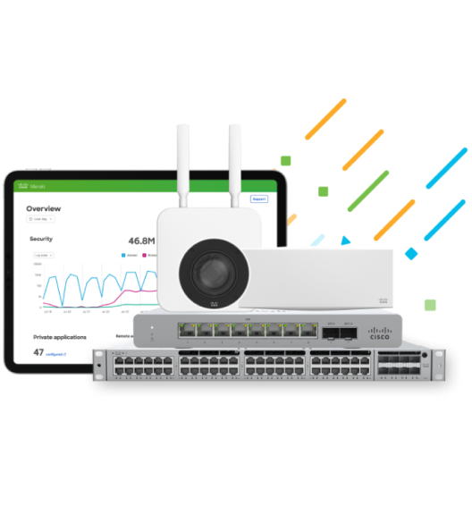
Spoiler alert: You'll save money
Get exclusive discounts to power your network‒including “One Year on Us”.