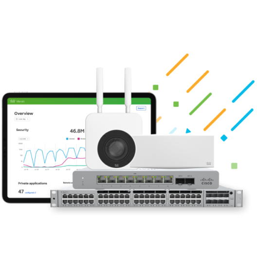
Meraki is excited to announce an extension to our growing line of multi-gigabit (mGig) switches with the release of the MS355.
The new switch features a high-count of full, 10G mGig switch ports and is designed to help IT admins of data-intensive networks prepare their organization to meet the demands of next-generation access points. Universities, hospitals, and large public complexes like transportation centers all benefit from the increased bandwidth capabilities of the MS355.
The timing is right for mGig switching. Analysts believe the rise of 802.11ax (AX) access points – also called Wi-Fi 6 – will overtake the current 802.11ac standard by 2020 and by 2022 comprise up to 87% of the wireless access point market.* These next-gen access points require more capable switches to handle the increased traffic.
*Dell’oro Group: Wireless LAN Five Year Forecast Report, 2018-2022
Enter High-Density Multi-Gigabit Switching
Multi-gigabit, or mGig, switches offer the benefit of greater switching capacity while using previously-installed Cat 5e/6/6a cabling infrastructure.
Not all mGig switch ports are the same. Switch device makers may designate a switch as mGig but cap the max bandwidth on the port to 2.5G or 5G. The device is still operable, but the smaller bandwidth size limits the potential of greater data rates in the future.
Notably, we previously dipped our foot into the water of full, 10G mGig with the release of our first multi-gigabit switch, the MS350-24X, which contained just 8 mGig ports for smaller deployments of mGig-capable devices.
For that reason, we developed the MS355, a cloud-managed high mGig port-density switch designed to help organizations prepare for large deployments of AX access points.
The series comes in four models all with 4 x 10G SFP+ ports, 2 x 40G QSFP+ ports, and 400 Gbps of stacking bandwidth. All models use 100 Gbps optical cables to stack up to eight devices for greater network resilience.
The series varies in the number of mGig ports included on the switch:
Troubleshooting network complications can be an extremely time-consuming and difficult process. Issues such as VLAN mismatch are tough to track down among the mountain of configurations needed to get a network operational.
VLAN mismatches occur when two ends of a link are misconfigured to different VLANs. These can happen over access or trunk links. A mismatch on the link that carries the critical traffic required to keep the network functioning – the Native or management VLAN – causes additional headaches and potential security concerns.
The above image represents a native VLAN configuration where management traffic flows untagged across the switch port links normally. The image below represents a VLAN mismatch.
When the switch port on Switch 2 is misconfigured to VLAN 20, the management traffic will continue to flow between Switch 1 and 2, but any traffic returning to Switch 1 is treated as VLAN 20. This mismatched scenario could result in traffic being altogether dropped or potentially be a security concern if VLAN 20 has access to confidential data not normally accessible to VLAN 1 and the data makes it to the destination device.
Meraki uses two methods to detect VLAN mismatches. The first method is to detect if the link is configured with the same VLAN type or number on each switch port of the link. The second method is to observe if the link is identically configured as an access or trunk (multiple VLANs) connection on both sides of a switch port.
To help users spot the issue, Meraki has implemented VLAN mismatch detection that notifies users when an error is found.
The dashboard now indicates when a VLAN mismatch has occurred on a specific port and what exactly is causing the mismatch.
With the notification, users can now immediately diagnose potential issues in seconds and quickly isolate which port needs to be correctly configured.
To find more information on how Meraki handles VLAN mismatches, head to our documentation page. To learn more about all of Meraki’s safety and security features for switches, consider attending one of our upcoming webinars.
An attacker wanting to eavesdrop on a network has several methods at their disposal to cause harm, notably with “man-in-the-middle” attacks where an attacking device pretends to be a valid member of the network to intercept traffic.
That method of attack is called “spoofing” which enables visibility into the device’s traffic and provides an option for attackers to use more aggressive network-disrupting tactics.
Device spoofing is a significant security threat, and it’s vital that your network have strong defenses. With our MS 10 firmware, Meraki is working to ensure your network remains secure with Dynamic ARP Inspection.
How does spoofing occur?
The attack works by deactivating the regular connection that switches use to pass information to client devices. The attacking device then misdirects traffic through itself by announcing its hardware address to devices that can hear it. The client devices aren’t smart enough to know the difference between the fake and real messages, so they begin forwarding potentially sensitive information to an attacking device.
The attacker can then spy on the traffic before forwarding the message to the correct device without anyone being the wiser.
How to defend against spoofing
Dynamic ARP Inspection (DAI) places safeguards at Layer 2 where bad actors may manipulate these important messages (ARP requests). DAI calls upon the network to verify whether the device handling the ARP requests is real or fake by checking whether that device has been seen before on the network. If the device hasn’t been seen, then messages from the attacking device are ignored.
Configuring DAI with Meraki is easy with MS 10. Note that to avoid disruption to your network, it’s essential to follow the steps in order.
In the Meraki dashboard, first, navigate to Switch > Switch Port and select the port associated with a DHCP Server or Relay. Select “Edit.”
Then navigate to “Trusted” and toggle to “enabled”.
Finally, navigate to Switch > DHCP Servers& ARP > DAI Status and select “Enabled.”
As with all things Meraki, the configuration of Dynamic ARP Inspection can be completed in seconds with our easy-to-use dashboard.
To learn more about other improvements in MS 10, please visit our documentation page or attend a webinar for a demonstration.
We are happy to announce the availability of our MS 10 firmware update for Meraki switches. The update introduces new features that improve the overall security, efficiency, and resilience of your network.
Let’s take a moment to review several of MS 10’s most notable features!
Security: Multi-Auth/Multi-Host
MS 10 introduces 802.1x Multi-Auth and Multi-Host authentication options to Meraki switches.
Multi-Authentication requires each host on a shared port to authenticate individually to gain network access. This log-in process is vital for network security in deployments with many autonomous clients.
Multi-Host Authentication allows a single host to open port access for subsequent clients after a single authentication. For example, someone using a desktop with multiple VMs would only need to authenticate a single time to gain access for all of her virtual machines. This reduces the frustration of needing to log-in multiple times when only a single authentication is needed.
Resilience: Enhanced Storm Control
Network storms occur when a set of switches endlessly forward packets between themselves, which clogs network bandwidth and causes normal network traffic to grind to a halt.
Enhanced Storm Control provides greater protection against network storms by allowing administrators to set limits on how much bandwidth can be allocated for certain types of traffic. If a storm does occur, damaging traffic will be limited to only a percentage of your total bandwidth capacity.
Resilience: Unidirectional Link Detection (UDLD)
Unidirectional link issues happen when a fiber cable is damaged or misinstalled and causes a loop that has the potential to disrupt the entire network.
A switch with UDLD prevents this type of loop by shutting down the port where a unidirectional link is detected. This keeps your network stable and more resilient against common causes of fiber-link errors.
Efficiency: Equal-Cost Multi-Path (ECMP)
Meraki uses OSPF routing which directs packets by determining the lowest-cost path to a destination. However, in situations where multiple equal-cost paths are available, some paths may be underutilized.
With Equal-Cost Multi-Path (ECMP), traffic is automatically load-balanced across up to 16 OSPF-learned paths which promote greater network efficiency.
Efficiency: Port Anomaly Detection
Port Anomaly Detection (formally called Spanning Tree Protocol /LAN Anomaly Detection) encompasses multiple enhancements for identifying and resolving spanning-tree and link issues. With the upgrade, the switch port icon indicates physical link errors and excessive link-status changes (STP issues). The individual switch ports will also display orange or red in the dashboard when these types of issues are detected.
More broadly, Anomaly Detection furthers Meraki’s mission of providing in-depth visibility into your network. By providing detection of erroneous network behavior, we help ensure network stability and scalability.
Increase your network’s resilience
If you would like to learn more about MS 10’s improvements, please visit our Knowledge Base or contact us directly.
For a full list of improvements, please login to your dashboard for more information:
Hot on the heels of our previous switch release (here) comes our MS210 stackable access switch.
We designed the MS210 to provide network administrators the option to stack the new 1G switch to the 10G uplink of the MS225.
Large enterprise networks often require multiple switches to handle office traffic but have only modest bandwidth needs per switch. However, many desire the flexibility to enhance their bandwidth capability as the organization’s tech needs grow.
The MS210 provides incredible power and flexibility to our switch line. Seven MS210s linked to a MS225 for its 10G uplink (to form a stack of eight) creates one of the most versatile and economical switch options available — all easily configurable using the Meraki dashboard.
The MS210 line features basic Layer 3 connectivity and comes in both 24- and 48-port models along with PoE and PoE+ power options.
When Stephen Stanton, VP of IT at A Wireless, was told about upcoming plans to acquire 370 stores across the United States, he didn’t think it would be possible. Stanton knew the company would not be able to scale at that rate with their legacy networking solution. But that was four years ago. Today, A Wireless, a full-service Authorized Verizon Retailer, has about 1,170 stores across 46 states—an almost tenfold increase in store locations.
On Thursday, February 9th at 10 AM PT, Stanton will join us in a live conversation to share how A Wireless evaluated and decided on Cisco Meraki as their solution of choice for national expansion.
As A Wireless acquired new stores, they also acquired a mix of IT networking solutions and vendor products. They found themselves with a network built on varying technologies, configurations, and management systems. Implementing a standardized network and centralized management was essential for their continued success.
Over a 3-year period, A Wireless have saved in excess of 80% in the total cost of ownership of the network, compared to a more traditional networking solution.
A Wireless TCO Cost Savings
Over 670 stores already fitted with a full suite of Meraki solutions, including MX Security Appliances, MR Access Points, MS Switches, and even a few MC Phones. Now, Stanton and his team are ready to deploy the next 500 locations with the same products and by the final deployment, all 1,170 stores will be full Meraki shops without any other network vendor solutions.
View a recording of this webinar, A Wireless, A Verizon Premium Retailer: Scaling Nationally with Meraki, here: [Link]
It’s never fun when your network suddenly stops working, especially when the problem turns out to be more subtle than those configuration changes you just saved. Even worse: your network seems to be smoothly humming along, but you’ve been compromised unknowingly. What could cause such catastrophic behavior? Rogue DHCP servers on your network.
DHCP is one of those Layer 2 protocols you never notice until it crashes or misbehaves. But, while DHCP may often be treated like the proverbial ugly stepchild, neglecting DHCP security comes with significant risk. After all, DHCP provides clients connecting to your network with IP addresses and configuration parameters such as subnet mask, default gateway, and DNS server information.
If these parameters become corrupted, the smooth flow of network traffic can abruptly halt. Worse, if a setting such as the default gateway is maliciously defined, network security is immediately jeopardized but you may not immediately notice. This makes detecting rogue DHCP servers paramount, especially given the ease with which they can be deployed.
Meraki’s switches operate at the same TCP/IP layer as the DHCP protocol and record which devices are sending DHCP server traffic. You can easily see if a non-authorized device is replying to DHCP requests from connecting clients.
View a list of all network devices replying to DHCP requests for the last month.
The image above shows that a device named Godzilla is replying to DHCP requests made by several clients on Meraki’s network. You can see Godzilla’s MAC address, as well as the VLANs and subnets it is servicing DHCP requests for. To get a more detailed view of any particular reply, you can click view packet:
View individual replies to client DHCP requests and learn what IP parameters may be corrupted.
This view provides the details of a DHCP server reply, including the IP address being offered to the connecting client and additional parameters such as lease time, subnet mask, default gateway, and DNS server information.
If Godzilla were not an authorized DHCP server, we could easily contain it. Simply search for Godzilla’s MAC address in the Monitor > Clients page to determine which switch and port it is connected to. Click into the connected switch and drill down to the individual port.
Port-level view of Godzilla, giving more details about the device.
Click “Edit configuration” and disable the port servicing Godzilla. This immediately disconnects the device from your LAN.
Port configuration settings allow you to disable a port and make several other useful changes
Detecting and disabling a rogue DHCP server is as simple as that. With the immediate threat contained, you can now track down the physical location of the rogue device. Re-enabling the port is as simple as repeating the steps above and selecting “enabled” in the port configuration menu.
Recent updates have made this DHCP server visibility possible at the switch level, so stay tuned for more posts detailing new features!