
MS450 Overview and Specifications
Overview
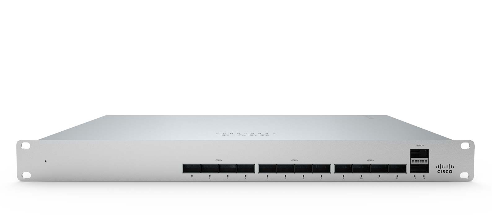
The MS450 aggregation switch features twelve 40G fiber ports (QSFP+) and two 100G (QSFP28) fiber uplink ports. The switch is designed to meet the needs of high bandwidth, multi-gigabit switching and works best alongside the MS355.
Features
|
|
Configuration
The basic initial configuration of the MS450 is just as simple as any other model of MS switch. The links below provide additional information and instructions relating to each step in getting the device setup and configured for the first time.
- Claim the device to an Organization on the Meraki Dashboard
- If a Dashboard Organization does not yet exist, Create one
- Add the device to a Dashboard Network
- If a Network does not yet exist, Create one first
- Physically connect the device to the local network
- Connect one of the RJ45 ports to existing infrastructure to provide a temporary uplink
- Power on the device and let it check in to the Dashboard
- If necessary, configure a Static IP through through the Local Status Page to allow it to communicate with the Meraki Dashboard.
- Allow the device to completely check-in and perform any initial firmware upgrades
- Finish configuring the device from the Meraki Dashboard
Context and Comparisons
| MS355-24X | MS355-24X2 | MS450-12 | |
| 1GbE RJ45 | 16 | - | - |
| mGbE RJ45 | 8 | 24 | - |
| 10GbE SFP+ | 4 | 4 | - |
| 40GbE QSFP+ | 2 | 2 | 12 |
| 100GbE QSFP28 | - | - | 2 |
| Hardware Stack Port | 2 | 2 | 2 |
| Dedicated Management Interface | 1 | 1 | 1 |
| Hot Swap Power Supply | Yes, Dual | Yes, Dual | Yes, Dual |
| Hot Swap Fans | Yes, 3x | Yes, 3x | Yes, 3x |
| Layer 3 Routing | Yes | Yes | Yes |
| UPoE Capable | Yes, 740W | Yes, 740W | No |
| Max Switching Capacity | 352 Gbps | 640 Gbps | 1.36 Tbps |
| Max Stacking Bandwidth | 400 Gbps | 400 Gbps | 400 Gbps |
Technical Breakdown
Hardware Breakdown
| MS450-12 | |
| 40GbE QSFP+ | 12 |
| 100GbE QSFP28 Uplink Ports | 2 |
| 100G Hardware Stack Ports | 2 |
| Dedicated RJ45 Mgmt Interface | 1 |
| Hot Swap Power Supply | Yes, Dual |
| Hot Swap Fans | Yes, 3x |
Throughput and Capabilities
| MS450-12 | |
| Layer 3 Routing | Yes |
| UPoE Capable | No |
| Switching Capacity | 1.36 Tbps |
| Stacking Bandwidth | 400 Gbps |
Physical
| MS450-12 | |
| Mount Type | 1U Rack Mount |
| Dimensions (h x w x d) | 1.72” × 19.08” × 18.85” (4.37 × 48.46 × 47.88cm) |
| Weight | 13.80 lbs (6.26 kg) |
| Power Supply | 250W AC |
| Power Load (idle/max) | 57W / 138W |
| Operating Temperature | 32°F - 113 °F 0°C - 45°C |
| Humidity | 5% to 95% |
Troubleshooting
Common Troubleshooting
My device is connected to the network but not checking in to the Meraki cloud or shows a solid Orange LED.
Confirm that the device is powered on and has a valid IP address that is able to access the Internet. Use the Local Status Page to get more information about the connectivity status of the device such as if it can successfully reach the Local Gateway, Internet, and/or Meraki Cloud servers. If necessary, contact Meraki Support for additional assistance.
My Status LED is blinking WHITE
A blinking WHITE Status LED indicates that the device is in contact with the Dashboard Cloud servers and is performing a firmware update. This can sometimes take 20-45 minutes or more to complete depending on hardware and other factors.
My Status LED is blinking ORANGE
The device is not able to successfully communicate with the Dashboard Cloud servers or there may be a hardware issue with the device. Check the Local Status Page of the device to confirm the status and reach out to Meraki Support for further troubleshooting.
Event Log
The most common Event Log messages and their meaning are listed below.
Port STP change
Indicates the STP state of the port has changed, lists the relevant port number, previous, and new states. Typically accompanied by a 'Port status change' event.
Port status change
Indicates the link state of the port has changed, lists the relevant port number, old, and new state. Always accompanied by a 'Port STP change' event.
SFP module inserted/removed
Indicates that an SFP module was either inserted or removed, includes SFP module information for inserted events and always lists the relevant port number.
Common Stacking Alerts
View our dedicated Switch Stacking document for more detailed information about configuring a Switch Stack and common issues.
Ensure all stack members are configured on dashboard, online and connected via their stacking ports.
Note: If connected and configured correctly, the alert will disappear within up to 1 hour. If the error persists, please contact Cisco Meraki Technical Support for further troubleshooting.
This switch's current stack members differ from the dashboard configuration.
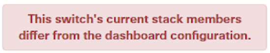
This error can occur in the following scenarios:
- Stack members are configured on dashboard, but not all members are connected via their stacking ports.
- A stack member has failed or is powered off.
This switch is not connected to a stack.
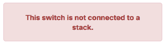
This error can occur in the following scenarios:
- The switch is configured on dashboard as a stack member, but is not connected to a stack.
This switch does not have a stack configuration.
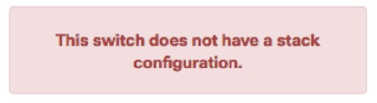
This error can occur in the following scenarios:
- The switch is physically connected as a stack, but not configured on dashboard as a stack member.
FAQ
Can the 100Gbps QSFP28 ports downshift to 40Gbps if 40G QSFP+ modules are used?
The 2 x 100Gbps QSFP28 ports are rated for 100Gbps use cases only. Downshifting to 40Gbps is not supported.
Is Flexible Stacking (similar to MS425) supported?
No, the MS450 has two dedicated stack ports to support physical stacking.